
I motorized my Ikea SKARSTA standup desk with an ATMEGA328P Arduino Microcontroller
This post is a follow-up from my previous one How I motorized my Ikea SKARSTA standup desk with an Arduino UNO, if you haven’t read that one, please do so first and then come back.
Warning
This setup is way more complex than the one on my previous post. If you’re looking for a quick and easy-to-follow guide to hack your desk and don’t have much time or knowledge of electronics then I strongly recommend you just go with my previous post. This post is for those that want a more solid feel, with better and smaller components, but it requires a lot more work.
Note: You can also go with my previous post and only update the Motor Carrier and Voltage regulators to use the ones from this one, it wouldn’t change much and you’d save a lot of space. you can also consider using an Arduino Mini instead of an ATMEGA328P.
Why do this?
It so happens my wife also has the same IKEA SKARSTA desk, and she got jealous at my desk being fully automated and hers wasn’t!, so I decided to improve this solution for the implementation on her desk:
- It feels like a big waste to use a whole Arduino UNO forever just for this, all we really need is the micro - an ATMEGA328P. It’s way cheaper, and it leaves my arduino ready to be used on the next project. (side note: keep in mind you can also simply use an Arduino Mini, but where’s the fun in that?)
- The L298N is extremely inefficient, dropping ~5 volts just for it’s use. I wanted a better motor carrier.
- The LM2596s Buck Converter is huge and very expensive, there must be a miniaturized versions of this.
- Any one of those jumper wires could very easily get pulled and the whole thing would stop working, I wanted something more robust, something soldered.
- The whole setup was a bit large for what it does, I wanted a smaller form factor for a better fit under the desk.
New Components
- ATMEGA328P (with Arduino Bootloader) - $5
- TB67H420FTG Dual Motor Driver Carrier - $10
- D24V5F9 9V Step-Down Voltage Regulator - $5
- Solderable PCB Breadboard - $3
- FT232RL USB to TTL Serial Converter Adapter (FTDI) - $2
- Soldering kit and cables - of course
What gets replaced?
From the previous post, you will replace the components as follows:
- Arduino UNO -> ATMEGA328P
- L298N -> TB67H420FTG
- LM2596s -> D24V5F9
Key differences in setup
The process in general is the same as with my original post, with a few differences, if you know what you’re doing you can probably simply look at these bullets and make the necessary adjustements on the fly:
- You will use a different branch (version) of my source code to account for the new TB67H420FTG motor carrier
- You can still use Arduino UNO to test the new carrier and voltage regulator etc. and then you can load the final version onto the ATMEGA micro using the FT232RL adapter
- You use the D24V5F9 voltage regulator to supply 9V of power to the ATMEGA328P
- You feed the full 29 V directly to the TB67H420FTG (don’t worry, it can handle up to 47V and deliver a continous 1.7A to each motor)
- Wiring is in general very similar, just accounting for new components.
I will detail the high level step by step process but focusing only on what’s different, again, please read my original post and then simply adapt the different parts as described below.
STEP 1: Configure drivers for the FTDI adapter
This is a pre-requisite to be able to later install the program onto the ATMEGA micro.
- I used Windows, download the drivers from https://ftdichip.com/drivers/vcp-drivers/, grab the SETUP one (CDM21228_Setup.zip).
- Connect the adapter FT232RL (alone, this is, without being connected to ATMEGA yet) using a mini-USB to USB cable to the PC and then run the setup, next->next->next etc., but they do have a detailed installation guide if you need it, and you should probably read the highlights: FTDI installation guide pdf
- Go to your Device Manager in Windows, and make sure it recognizes it as a USB Serial Port:
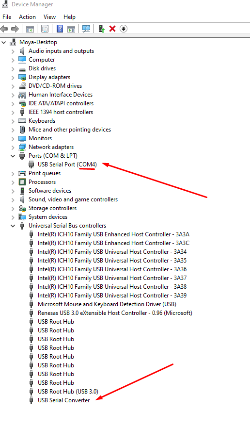
- Take note of the COM port number it assigned, you will use it on Step 3-b.
STEP 2: Special wiring for ATMEGA328P program loading
For this step you need to use a separate solderless board with a special wiring to be able to burn the program onto the ATMEGA328P plus a few components, you will use the same source code as above.
For the wiring, I followed many of the instructions from the https://dronebotworkshop.com/arduino-uno-atmega328/ page, using the FTDI adapter section, I think it’s very easy to understand, and I’m leveraging pictures from them. Please visit their page for more details if necessary, they also have an excellent video.
I’ll try to summarize:
Extra Components:
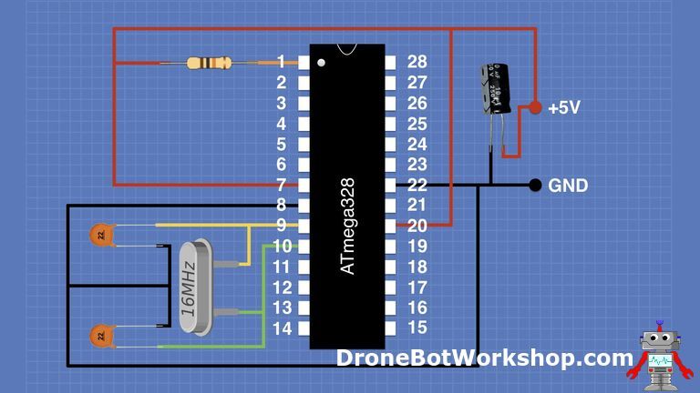
- A 16MHz crystal.
- A 10K resistor.
- Two 22pf capacitors.
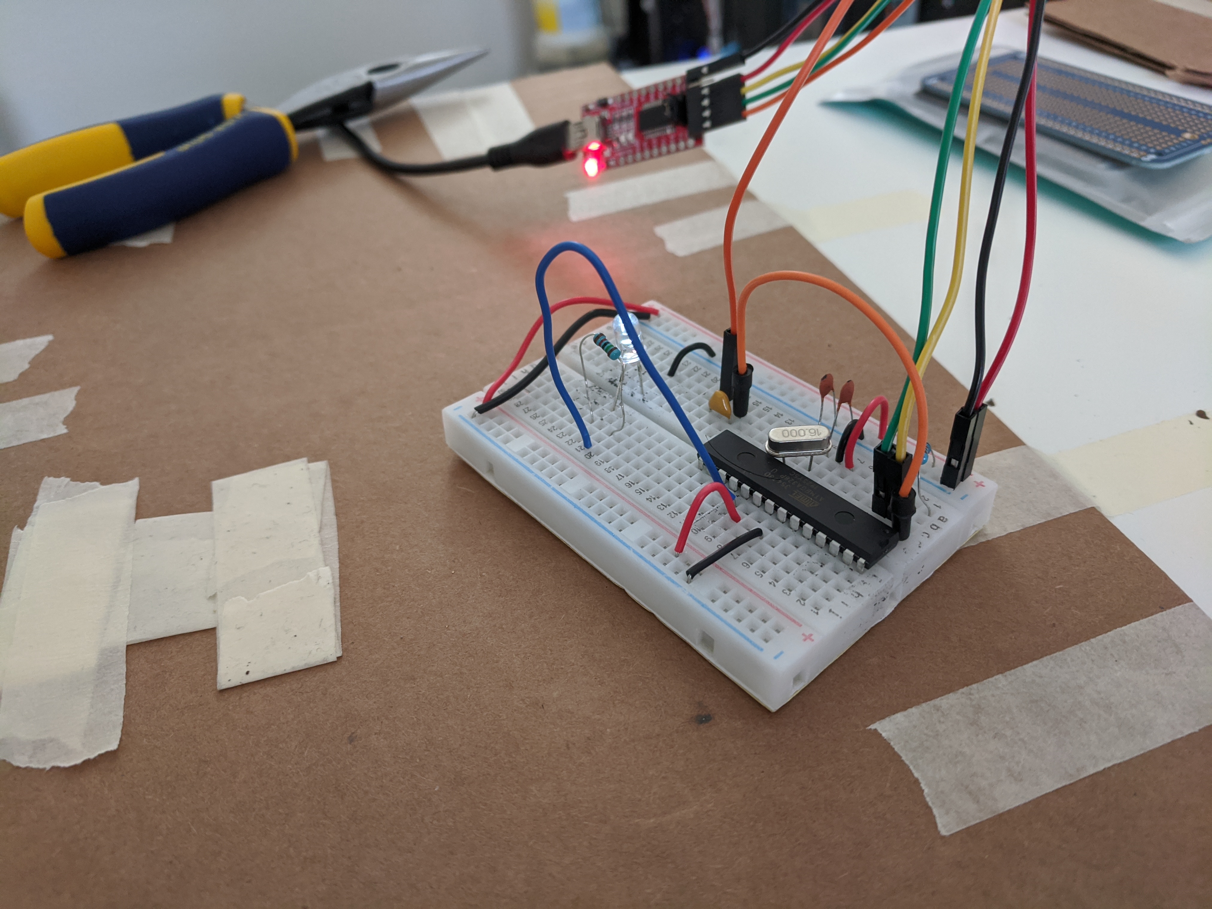
Wire it up like this (again shout out to dronebotworkshop.com for the pics):
Then IN ADDITION of the previous wiring, connect the FT232RL adapter as follows:
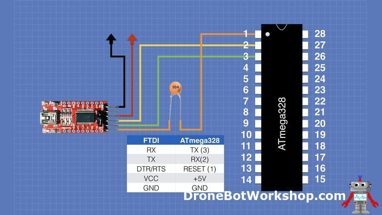
It should look like this:
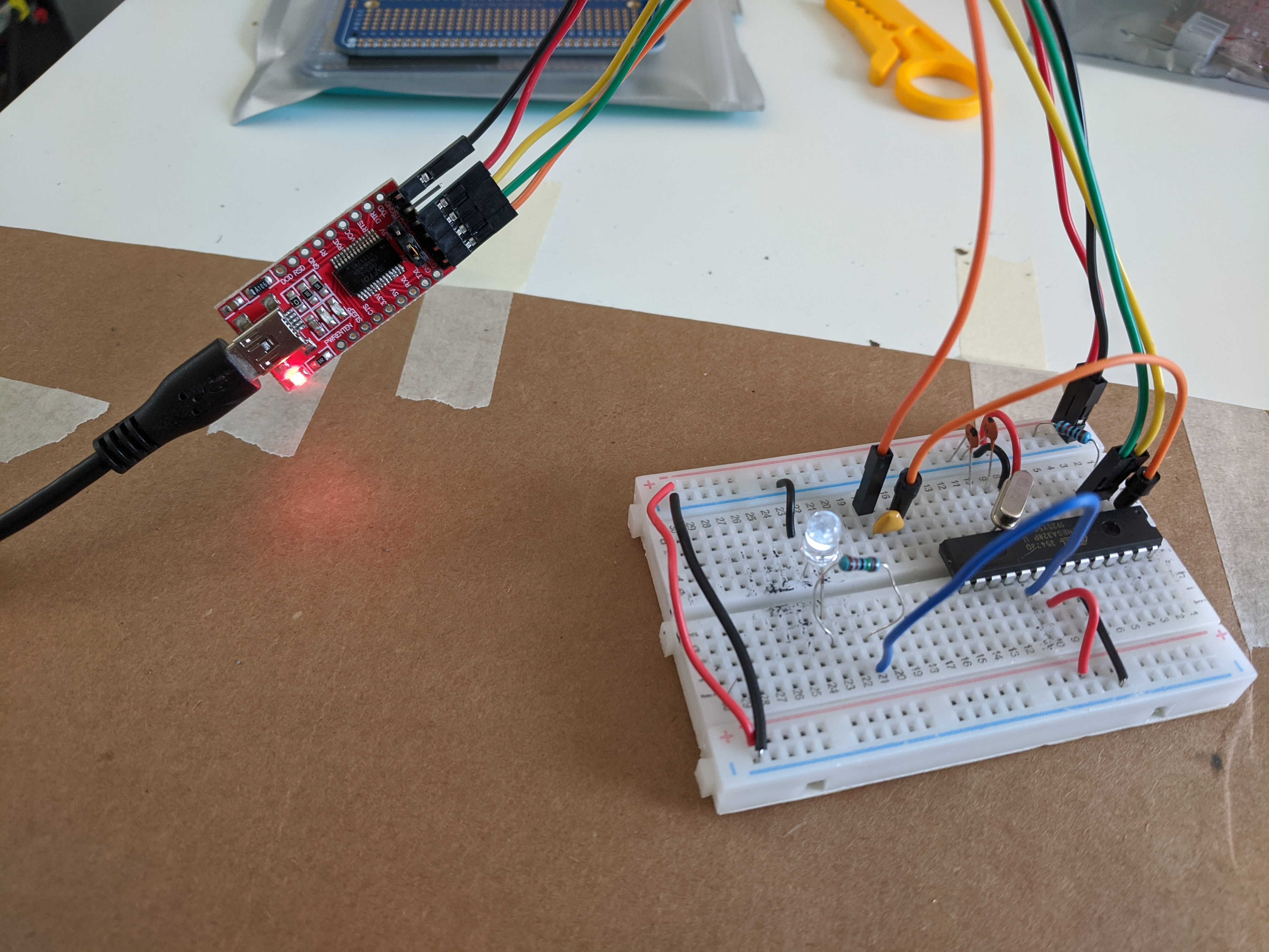
Now this is ready to load the program onto it. You could choose to go to Step 3-b directly if you want to skip the Arduino test, but you will likely need a few iterations to adjust your PWM values to fit your requirements so I strongly recommend you first do Step 3-a, then wire it all up and test it, and only AFTER you’ve confirmed all works go to Step 3-b for final program load. Don’t worry, you can load the program onto the ATMEGA328P as many times as you need, it’s just a bit more of a hassle because you have to physically remove the micro from one board to the other, hence, using Arduino first is much faster for testing.
STEP 3-a: Load the program (on Arduino UNO)
I recommend to load the program on the good’old Arduino UNO first, and wire it all up using jumper wires and test it to be able to quickly make any necessary adjustements to the PWM signals etc. Once it’s properly configured, load it to the ATMEGA as described on Step 3-b below.
- Grab the new source code: dualmotor-tb67h420ftg-29v branch
- The programming of the TB67H420FTG Motor carrier is a bit different, mainly the digitalWrites in the goUp and goDown functions as they use a different in1/in2/pwm combinations, for more details consult the table on the “Using the motor driver” section of the carrier page
- Test the program on a regular Arduino UNO first using the default values of the
#definevariables, tweak any changes you might need (namely, the PWM_SPEED_UP and PWM_SPEED_DOWN variables)
The pins numbers used are different, but the mapping is in the source code in the form of a comment. e.g. #define BUTTON_DOWN 2 //ATM-4, means use the pin 2 on Arduino UNO, but use the pin 4 on ATMega for that function.
Step 3-b: Load the program (on ATMEGA328P)
If you’re ready for this, grab your secondary board with the ATMEGA fully and properly wired as explained above, including the FTDI adapter fully wired too, then:
- Plug it in to your PC using the mini-USB to USB cable
- Open the code dualmotor-tb67h420ftg-29v branch in Arduino UNO IDE
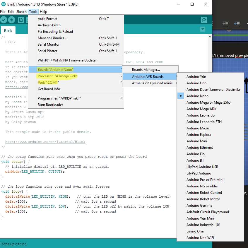
- Go to Tools -> Board -> Arduino AVR Boards -> Arduino NANO
- Ensure that the Tools -> Processor is “ATmega328P”
- Ensure that the Tools -> Port is (whatever COM# it assigned on Step 1)
Should look something like this:
You should be able to compile and upload. The lights on the FTDI will blink very fast while the program is loaded.
Note: You can use the Tools -> Serial Monitor tool to output debug messages from the code to monitor behaviour on your ATMEGA program. I found this very useful to confirm that my program was actually loaded correctly and that access to the EEPROM memory worked.
STEP 4: Wire it up
This step is a bit flexible, in general the wiring is similar whether you’re using the Arduino UNO or the ATMEGA to test, but there are differences, I suspect if you’re reading this article and made it this far you probably know what wiring to modify from my previous post to make it work with the new motor carrier and voltage regulator so I won’t upload a diagram for that, simply look at the wiring specs for the new pieces and wire accordingly onto the same setup.
As for the ATMEGA328P wiring, you need to first do the “base wiring” we did on Step 2 (the crystal and stuff, but not the FTDI), and then on top of that connect the appropriate pins to supply voltage, ground, and the pins that receive/send the signals as defined in the code and in the equivalence picture below.
The key thing to understand here is that there is a 1 to 1 mapping to every pin from Arduino Uno to the ATMEGA238P, see the following picture:
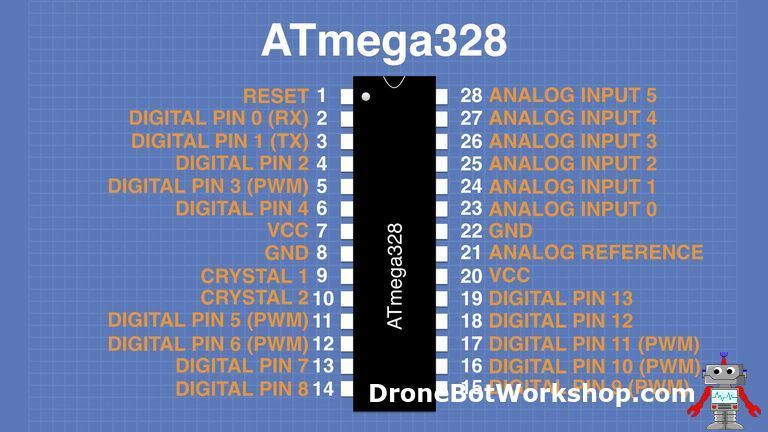
In other words, the text in orange is the Arduino Uno equivalent, for instance: Arduino’s Digital PWM pin 6 = ATMEGA’s pin 12. You will notice on my code I have the appropriate mapping commented out on the #define section. So, all you need to do is, again, use the knowledge from the wiring from my previous post, and simply adapt it so that you use the new pins as defined in the code, plus being careful to supply the ATMEGA from the nice and steady 9V output from the D24V5F9 regulator - of course.
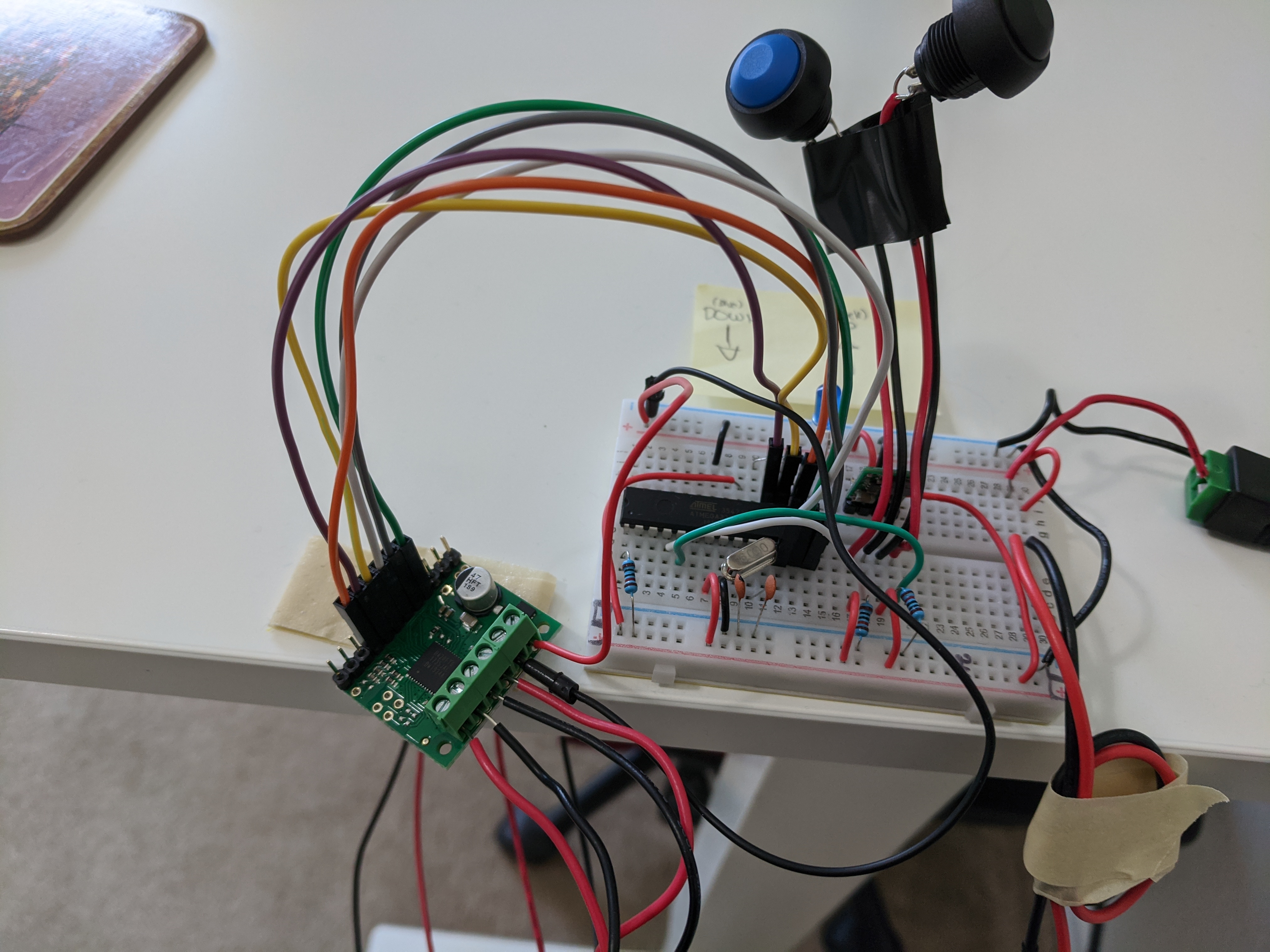
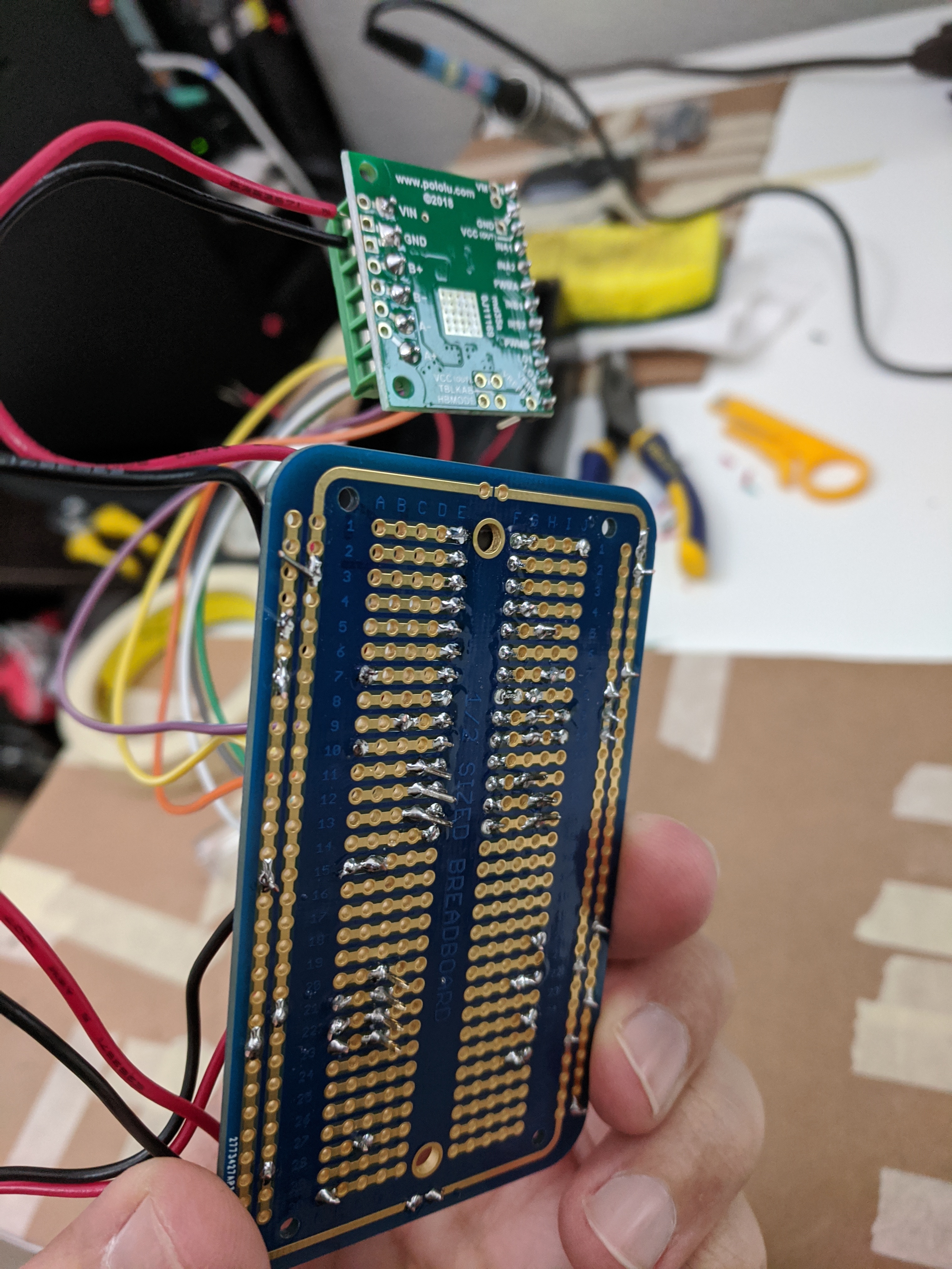
Again - I recommend you wire it up in solderless boards first, then test, then you can solder the final product onto a solderable board:
Final product (soldered) should look like this:
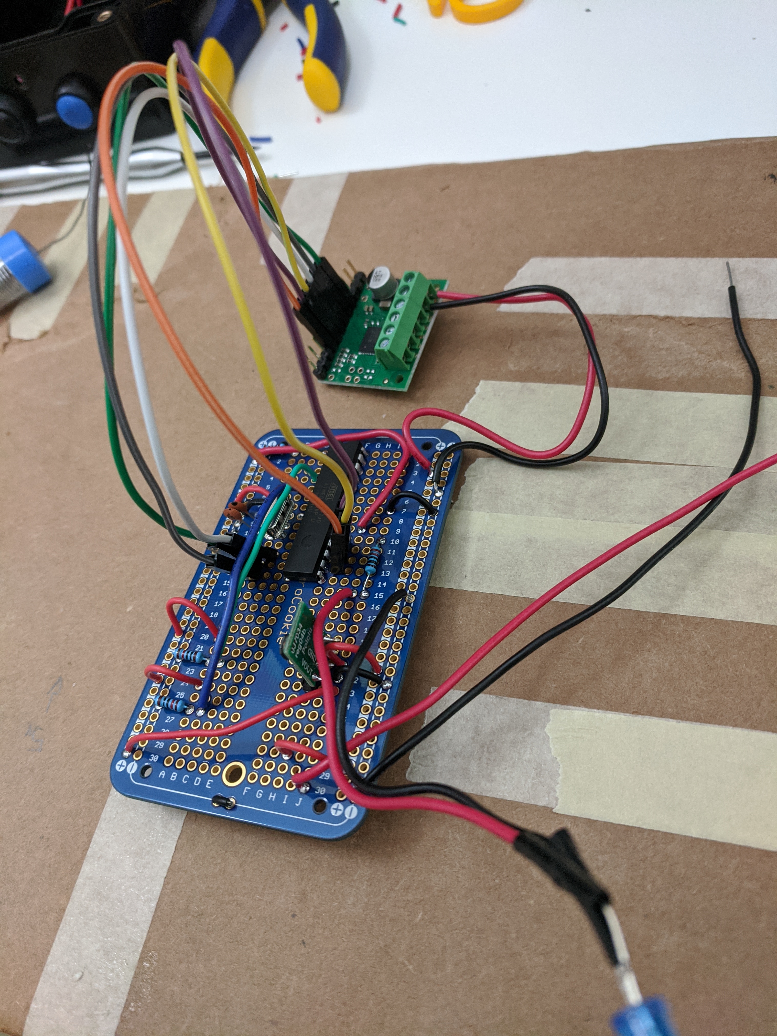 Look at that solder!
Note: I didn’t think it was necessary to create another circuit diagram for this, if you absolutely need it let me know in the comments.
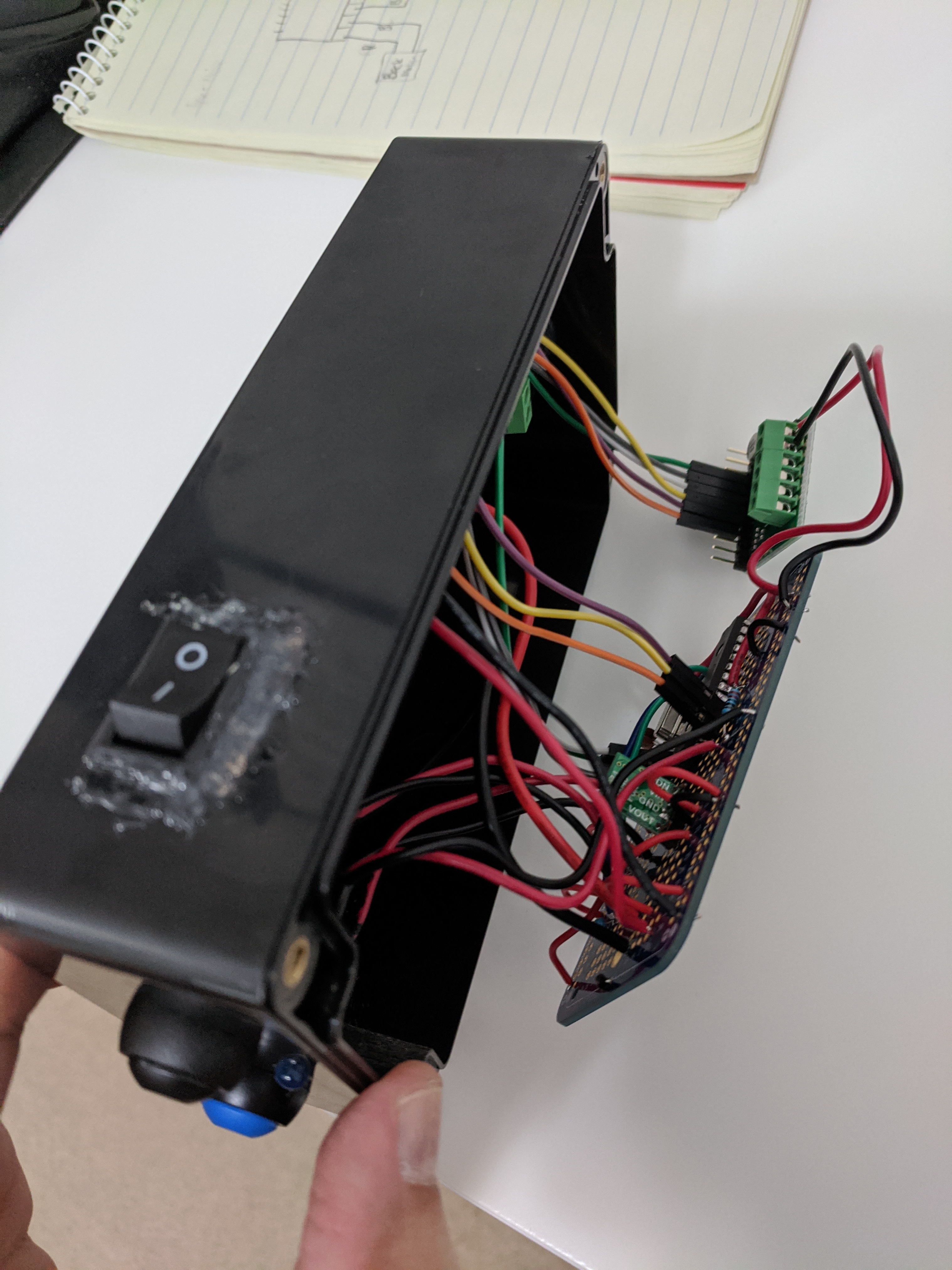
STEP 5: Enclosure
Same steps as on my previous post, but I wanted to show a picture before closing up!
Conclusion
Using an ATMEGA328P and soldering everything is a way more complex project than the previous one, but the satisfaction and end product does feel a lot more solid, smaller and professional. I had a lot of fun doing it and learned a million things, I hope you enjoy it too.
As always, feel free to leave any comments below.
Comments